Blog
Bringing closed-loop automation from theory to practice

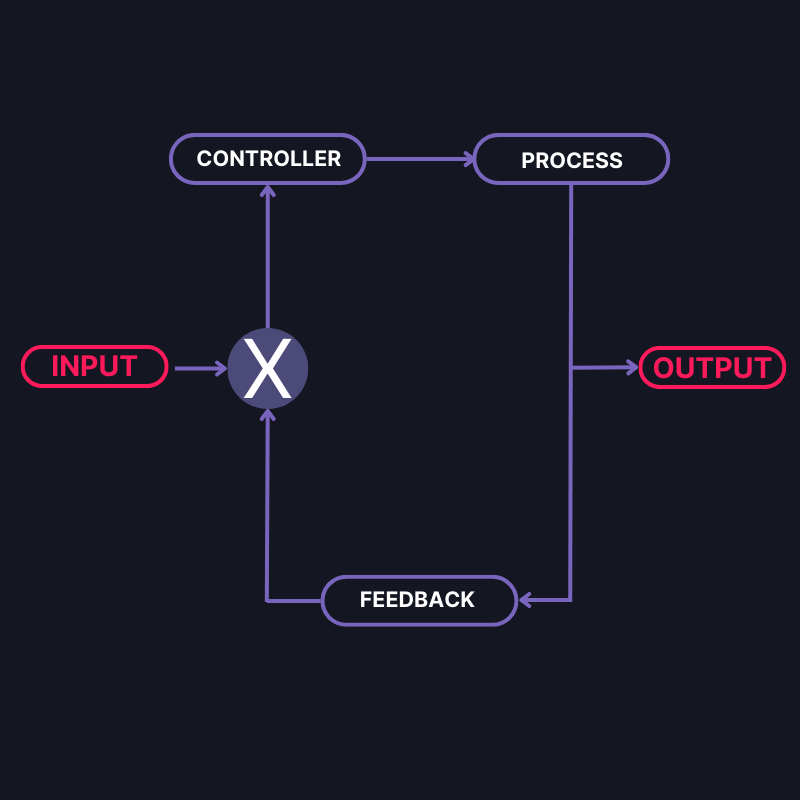
What is Closed-Loop Automation?
Closed-loop Automation is performing/automating a self-adaptive output process based on meaningful insights derived from continuous data collected by a system without human interference. In other words, automatically bridging the gap between Data → Insight and Insight → Action. Although this concept is well-recognized in academia as “self-adaptation”, it has yet to be implemented in industry.
In Closed-loop Automation, the necessary actions are identified based on knowledge and input information. Thus, data is the critical component. With good data and robust algorithms, systems can run without human intervention. Closed-loop Automation results in improved reliability, increased productivity, and a reduced mean-time to resolve incidents.
The heart and brain of industrial automation
Programmable Logic Controllers (PLCs) are industrial computers controlling various processes in manufacturing and other automation environments, often called the heart and brain of industrial automation. In industrial automation, PLCs have revolutionized factories by transforming traditional manual labor processes into efficient, machine-orchestrated factory operations. However, even with technologically advanced automation infrastructure in place, manufacturing factories face significant challenges when it comes to downtime, for e.g., human related downtimes, complex system failures, planned and unplanned downtimes.
With the increasing complexity of manufacturing processes and the dynamic changes in demands of market and factory goals, mitigating downtime has become crucial. Traditional approaches to automation often lack the adaptability and flexibility to efficiently handle downtime-related tasks. One particular area that requires improvement is the reconfiguration processes of the Programmable Logic Controllers (PLCs) during manufacturing operations.
Optimizing machine commissioning time using SDA PLC Ops
Commissioning a new machine to an existing shop floor is complex and time-consuming. A traditional commissioning process for a new machine controlled by a PLC involves a significant amount of PLC code testing and iterations being made to the PLC code of not only the new machine but also to the connected machines which are already installed on the shop floor. With the increasing complexity of machine behavior and user requirements, ensuring a smooth and faster commissioning process using this legacy approach is evolving into a limiting factor in the digital journey of manufacturers. The need for building self-adaptive systems is inevitable where in this case, the PLC should self-adapt to the shop floor requirements and ease the commissioning process to reduce labor, time, and cost.
Software Defined Automation is bringing closed-loop automation from theory to practice
SDA built a setup to showcase the commissioning of a new machine to an actual factory shop floor with the help of two motors. The leader motor represents the existing assembly line process, and the follower motor represents the new machine that needs to be commissioned. PLCs control these motors and the commissioning process is showcased by reconfiguring the PLCs to synchronize the motor speed parameters in the PLC program. Successful commissioning of the new machine to the existing assembly line process is determined by the successful synchronization of both motor speeds by performing the PLC self-adaptation.
Our team of engineers has performed the PLC self-adaptation process to demonstrate the PLC reconfigurations and auto-generation of PLC projects in response to changes detected through real-time data insights using cameras, programmatic upload of PLC projects to the cloud and automated deployment using APIs, all powered by SDA PLC Ops.
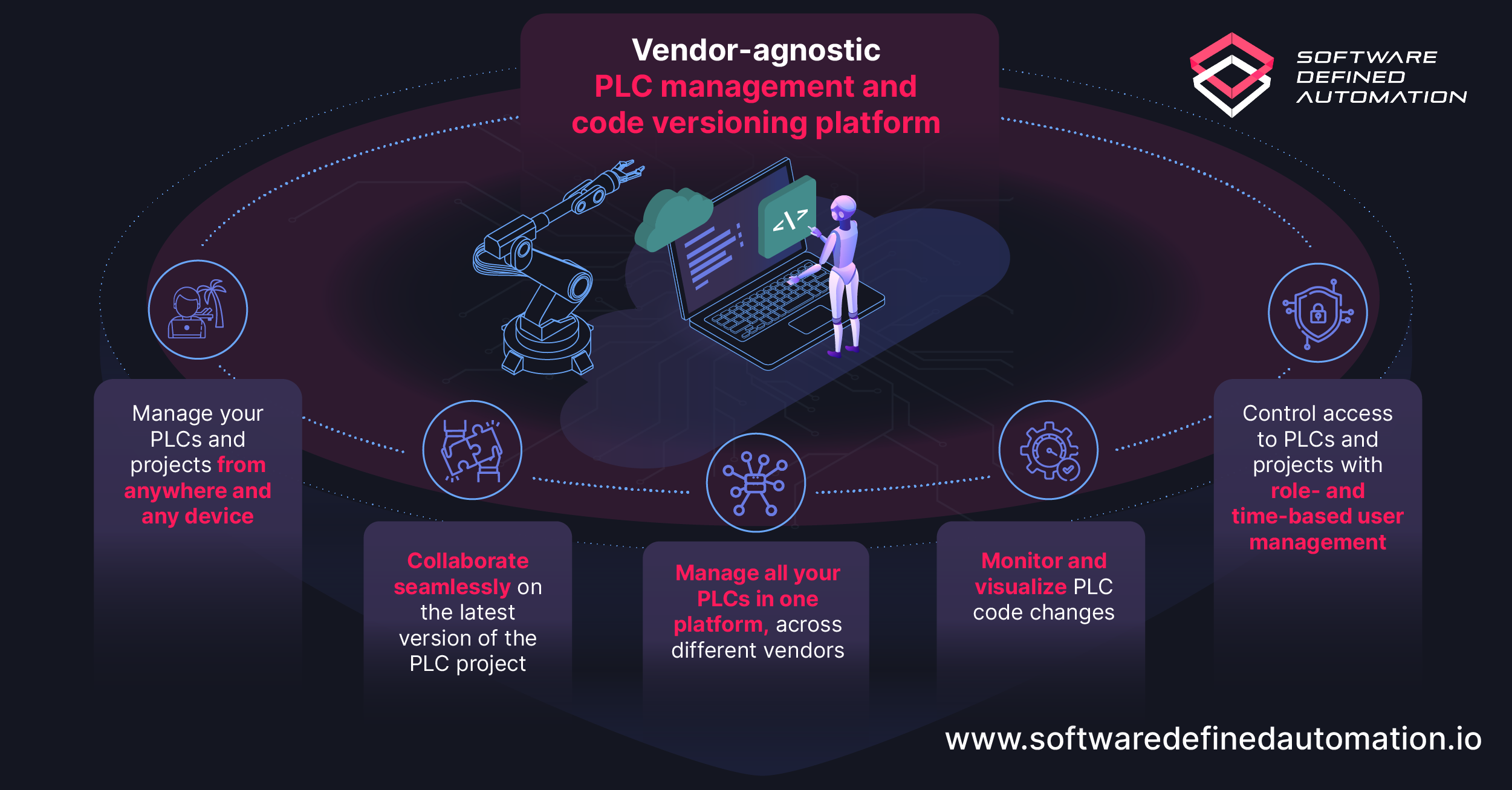
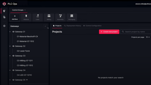
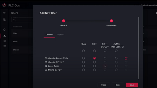
SDA PLC Ops is a cloud-based PLC operations platform for conventional and virtual PLCs, across different vendors. It enables uploading, downloading, and versioning of PLC projects, as well as automated code deployments directly from the cloud to PLC without opening vendor-specific IDEs.
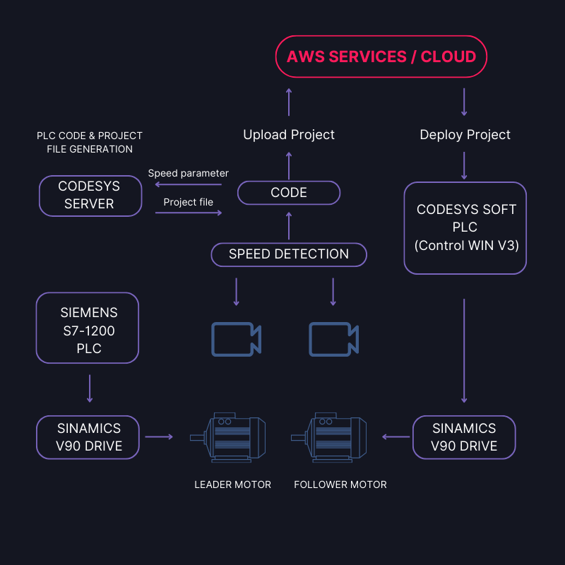
The experimental setup consists of the following components:
- Two SIMOTICS S-1 FL6 servo motors driven by SINAMICS V90 servo drives. The leader motor is controlled by a Siemens SIMATIC S7-1200 PLC, which can change the speed of the motor in increasing steps of 10rpm with the help of a button. The follower motor is controlled by a CODESYS SoftPLC (Control Win V3) which is linked to the SDA console via a preconfigured gateway.
- Two high-resolution cameras monitor the physical process and provide data about the speed of the motors.
- A vision detection model that calculates the RPM of both motors using OpenCV library and detects the difference in speed.
- CODESYS “scripting engine” for accessing CODESYS APIs to use functionalities like importing and exporting “PLCopen XML” files and generation of new PLC project file.
- The Software Defined Automation platform provides solutions like SDA PLC Ops to link and manage PLCs and PLC projects and enables the “Silent Deploy” feature to deploy PLC projects directly from the cloud to the physical PLC.
- A Python program that functions as a state machine to integrate all the above components and controls the entire process.
The main objective of this experiment is to show that when a difference in speeds of both the motors is detected, the system should self-adapt to synchronize their speeds by:
- Using vision detection cameras to detect a difference in the speeds of both motors
- Auto-generating PLC code and project with the above-detected speed of the leader motor
- Uploading and storing the newly generated PLC project to the SDA cloud platform and,
- Deploying the project from the SDA cloud directly to the PLC connected to the follower motor without the need of human interaction.
Putting it into practice
The figure below shows the elaborate version of the MAPE loop which has been used in this demo to put theoretical concepts into practice.
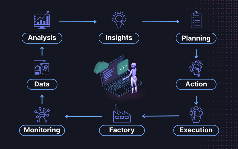
The self-adaptation process for PLC reconfiguration is performed in 4 stages of the MAPE loop as follows:
Monitoring stage (Speed detection stage):
The vision detection cameras detect the real-time speed of both motors using OpenCV modules. The frames captured by the cameras are used to detect these circles and their respective speeds. The figure below shows the OpenCV windows detecting the circular plates attached to the motors.
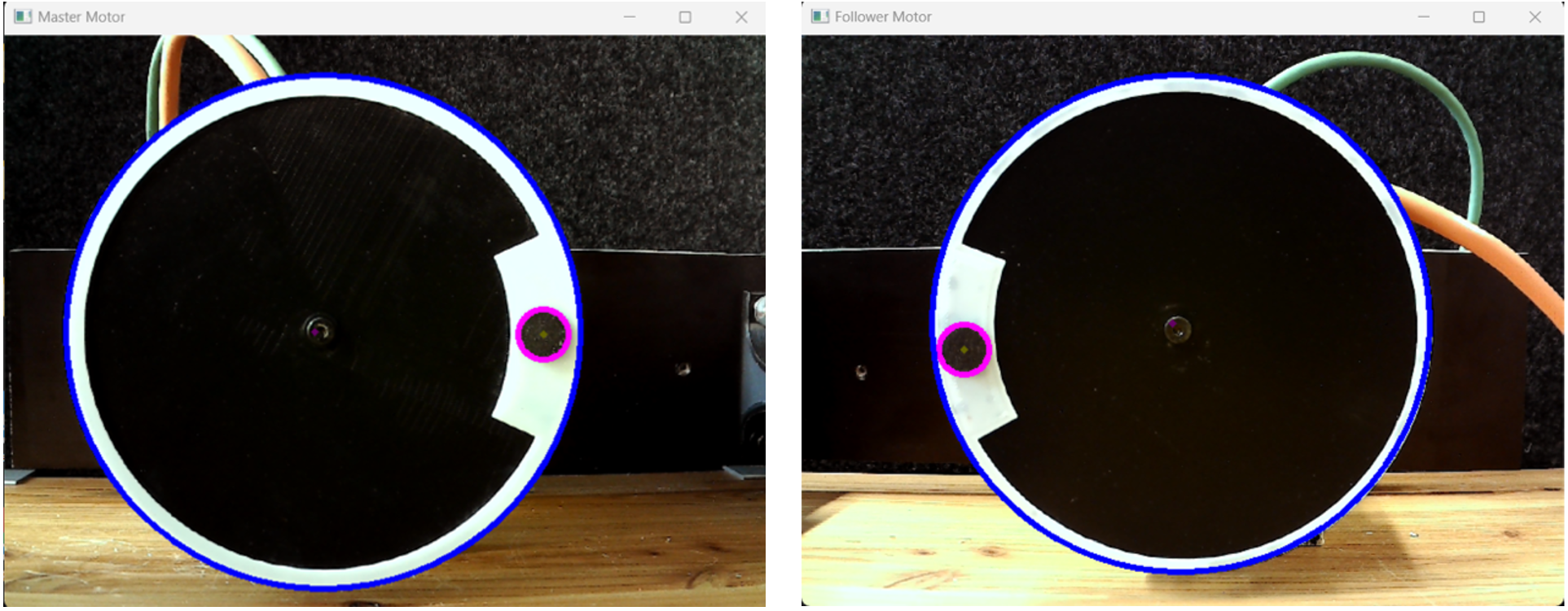
Both motors’ speeds data are collected simultaneously and stored in two separate files on the local PC. In this case, the cameras detect the leader motor running at 10 RPM and the follower motor is stationary. This collected data can further be used to analyze, gather insights, and plan the next course of action.
Analysis stage (Insights generation):
The collected data from the monitoring stage is analyzed to check whether the two motors are running at the same speed or not. Suppose the speeds of both the motors (leader and follower) are not equal for three consecutive data points. In that case, the program triggers the initiation of the planning stage where the speed of the leader motor is given as input to plan a sequence of steps to generate PLC code and project for the follower motor to synchronize both motor speeds.
Planning stage (Auto-generation of PLC code and project):
A CODESYS IDE is instantiated asynchronously in the SDA PLC Ops environment, which facilitates the use of CODESYS “scripting engine” and CODESYS APIs. These APIs enable the opening of an existing PLC project for the motor and extracting the PLCopen XML file of the project. This PLCopen XML file contains all the information of the PLC project and is modified using XML processing to change the variable value of the output speed of the motor. This updated PLCopen XML file is then imported back into the CODESYS IDE to generate and save a new PLC project with updated output speed.
Execution Stage (Programmatic upload & deploy of PLC projects)
With the “Planning stage” completion, the new PLC project file with updated PLC code has been successfully generated.. This project file must be deployed to the CODESYS SoftPLC which controls the follower motor to complete the synchronization process.
Project Upload to SDA cloud – The newly generated PLC project is uploaded to the SDA console using the SDA PLC Ops solution. The file is uploaded and stored in the SDA cloud using REST APIs and is linked to the CODESYS SoftPLC.
Project Deploy to PLC – SDA’s “Silent Deploy” feature is used to perform programmatic deployments directly from the SDA cloud to the PLC
The closed-loop process is completed and both the motors now run at the same speed (in this case 10 RPM). The cameras detect the same speed on both motors and acknowledge the completion of the synchronization process. The speed detection loops until a new difference in speeds of the two motors is detected and executes the above processes again.
Results
A set of 50 experiments has been performed using the PLC self-adaptation. Each experiment constitutes the 4 stages of the MAPE loop. The time required for auto-PLC code and project generation, project upload to the cloud, deployment of the PLC project from cloud to the physical PLC and the total adaptation time is recorded.
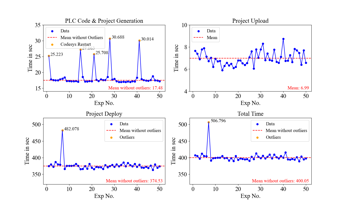
The scatter plots provide accurate information about the time required to complete individual stages by each experiment. By excluding the outliers, the mean for total time required to perform the complete PLC self-adaptation is observed to be approximately 400 seconds (6 minutes 40 seconds).
In reference to the commissioning of a machine to a factory shop floor addressed in this experiment, the time required to perform multiple iterations manually during commissioning by an automation engineer is a very long and laborious process. However, by implementing the PLC self-adaptation technique, the results show that the commissioning process can be performed in merely a few minutes without human interference with continuous adaptations based on insights gathered from real-time data. This relieves the automation engineer from a substantial workload and only acts as a supervisor for validating the process.
These results provide a proof of concept of using closed-loop automation for rapid PLC adaptations as we:
- Performed PLC self-adaptation using MAPE loop in approximately 6 minutes 40 seconds, also showing potential for optimization in the near future.
- Achieved auto-generation of PLC code and project.
- Successfully implemented upload and deploy of PLC project from AWS cloud to physical PLC.
- Completed the entire cycle without human intervention.
We conclude that such resilient systems, which rapidly adapt to changing operating conditions, are needed in today’s industries to facilitate increase in overall productivity and efficiency of factory operations and a decrease in downtime.
Closed-loop Automation can be implemented in many other industrial processes, like assembly line changeover, predictive maintenance, scheduling, process optimization and many more.
Stay up to date. Subscribe for our latest news.